1. Constant Voltage
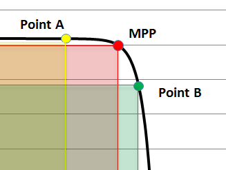
Constant voltage maximum power point tracking was one of the first ever created algorithms and has the most limitations. Constant voltage MPPT simply measures the ambient temperature of a modules surroundings and adjusts the voltage accordingly. The constant voltage algorithm requires very little electrical hardware to implement and can provide acceptable power increases with little cost. However, constant voltage tracking completely overlooks solar irradiances impact on the MPP of a module and therefore lacks the ability to truly find the maximum power point. This method was one of the first introduced into the industry and is seldom used today, but was an important step in MPPT research and development.
2. Open-Circuit
Open circuit maximum power point tracking relies on the fundamental idea that the maximum power point of a solar module is always proportional to open circuit voltage. Electrical circuits are set up within the MPPT channels to calculate instantaneous open circuit voltage and then sets the module to a voltage proportional to that open circuit voltage. Substantial testing has been done surrounding open-circuit MPPT and the most common module voltage is determined using the simple proportional relationship below, where Vmod stands for the voltage of the module and Voc represents open circuit module voltage.
-
Vmod = 0.76 * Voc
Similar to constant-voltage MPPT this algorithm does not require elaborate electrical equipment or setup and can be implemented using rather basic computations. However, this algorithm has two main limitations that have kept it from being adopted as a main, widespread MPPT method. First, the proportionality constant, which I presented above as 0.76, can change substantially depending on the cells used in modules, which presents a slight challenge. Second, in order to measure the open circuit voltage of the solar array, the MPPT channel must create a short circuit, which disallows solar harvesting and can put serious stress on electrical wiring.
3. Perturb & Observe
Perturb and observe has been and currently is the most widespread MPPT algorithm. The implementation of the algorithm is relatively inexpensive while being very robust and effective. The idea behind P&O is essentially like playing a game of tag with the maximum power point of a solar module. This method measures the power output of a solar module/array and then changes the voltage supplied to that panel. After, the system will measure the power output again and compare it to the previous power output. If the power went up after increasing the voltage, then the system will increase the voltage once again in search of finding the MPP. However, if increasing the voltage on the module leads to a decrease in output power, the system will provide a voltage decrease to the module next time increment. Using this algorithm, the voltage is always changing, and when it leads to an increase in power, the system will continue to increment the voltage in the same direction. Industry standard falls around a 2-volt standard increment or decrement for every cycle.
Perturb and observe is a very well documented and respected method of MPPT, but still, has some reasonably substantial limitations. First, due to the nature of the process, this algorithm will never let a module stay at the exact maximum power point because the voltage is always changing and oscillating close to the MPP, but never actually landing and staying on it. Smaller changes in voltage every cycle leads to a smaller bumper around the precise MPP, but regardless, the MPP will always oscillate around the ideal voltage. Moreover, making the incremental voltage smaller will inhibit the system's ability to respond quickly to changes in temperature or irradiance. For example, if a cloud flies over the sun and shades the modules, that drastically changes the module irradiance levels and the P&O method will take a very long time to find the new MPP. The reason behind perturb and observe not reacting well is because it will have to cover a large voltage change by making small incremental voltage changes and testing against the previous voltage. The aforementioned thought of decreasing the size of voltage change will make reacting to quick irradiance shifts even more difficult as the system will be forced to increment tens, hundreds or thousands more times before reaching the eventual MPP, which could very well shift right back when that cloud passes.

4. Incremental Conductance
The incremental conductance algorithm is considered one of the most effective methods to track module maximum power points. This method uses the instantaneous rate of change of power with respect to voltage (dP / dV) to find the maximum power point. Along with the above derivative, the relationship between dI / dV & -I / V is a cornerstone piece of the incremental conductance algorithm. Several mathematical equations are monitored by the MPPT system, and, without getting too far into the numbers, the table below shows the basic computations that the module will make.
|
dI / dV = -I / V & dP / dV = 0 |
Module voltage is at MPP |
|
dI / dV = -I / V & dP / dV < 0 |
Module voltage is above MPP |
|
dI / dV = -I / V & dP / dV > 0 |
Module voltage is below MPP |
Incremental conductance is far and away the most mathematically demanding of the four presented MPPT methods in this article. Because of the complexity of the method, it optimizes energy output very well but certainly has some drawbacks.
The sheer computational requirements of an incremental conductance system force electrical equipment to be far more expensive than comparable MPPT systems. Similarly, the system needs more components than many of the electrical circuits that it competes with. Putting these two realities together, creating an incremental conductance system can be extremely expensive and difficult, which is certainly one of the main limitations. From a performance perspective, incremental conductance does an extremely good job covering large changes in irradiance because it can change voltage levels to the exact MPP right when any irradiance changes. Moreover, it does not oscillate around the true MPP like perturb and observe does, which makes it a much better option for times when the MPP will not be changing often. Lastly, while IC does track big changes well, it generally takes longer than P&O to react to the changes in voltage and make adequate corrections because it takes more time to measure all the important electrical factors. In the end, incremental conductance has been experimentally proven to produce more output power compared to all its MPPT algorithmic counterpoints, so depending on your budget, it might be a great solution.
Quick Comparison
Perturb and Observe |
Incremental Conductance |
|
Relatively inexpensive |
Relatively expensive |
|
Oscillates around exact MPP |
Does not oscillate around exact MPP |
|
Reacts quickly to small changes in temperature and irradiance levels |
Reacts slowly to small changes in temperature and irradiance levels |
|
Inefficient at tracking large shifts in temperature and irradiance levels |
Swiftly tracks very large shifts in temperature and irradiance levels |
Works Cited
- Ratna Ika Putri, Sapto Wibowo, Muhamad Rifa. “Maximum power point tracking for photovoltaic for incremental conductance method.” Energy Procedia, vol. 68, 2015, pp. 22-30. https://www.sciencedirect.com/science/article/pii/S1876610215005342
- Saleh Elkelani Babaa, Matthew Armstrong, Volker Pickert. “Overview of Maximum Power Point Tracking Control Methods for PV Systems.” Journal of Power and Energy Engineering, 2014, no. 2, pp. 59-72. https://file.scirp.org/pdf/JPEE_2014082811233330.pdf


