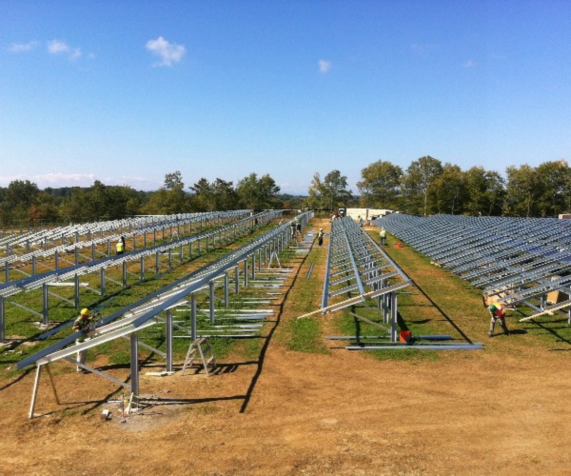
Ground mounted solar arrays range in size from small residential <10 kW arrays to large utility solutions upwards of 1 MW and beyond. Within that range, there are many, many racking options available to meet the needs of almost any site and any project. The following is a general overview of available options.
Before choosing a specific ground mount system the designer must perform a thorough site assessment that includes a geotechnical study. This will define the parameters of design, help reduce risk during the construction phase and allow the designer to choose a proper ground mount solution.
Ground mounted arrays are installed at grade on galvanized steel and / or aluminum support structures. The support structures are bound to the earth using foundations consisting of driven piles, helical piles, ground screws, concrete footings, concrete ballast or a mixture of these components. The type of foundation used is based mainly on soil properties as well as the geometry of the foundation.
There are two basic types of foundation geometries, single post and double post. Single post foundations are those where a single row of foundations support the racking structure - see Figure 1 below of the AET Rayport-G ECO solution. The single row of posts are aligned along the length of the array towards the center to rear ¾ of the front-to-rear array dimension. Various racking configurations are available to install. The most common consists of cantilevered struts and braces making up the strongback which resembles a "number four" in profile. Module rails are installed spanning the strongbacks along the length of the array.
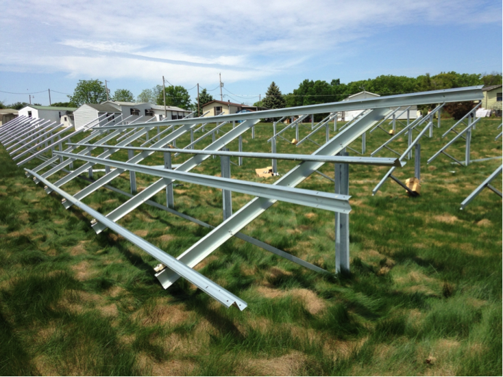
Figure 1. AET Rayport-G Eco - Single Post
Double post foundations use two rows of foundations (one front and one rear) to support the racking structure - see Figure 2 below of the Unirac ULA solution. In this configuration horizontal supports span the foundations for each of the rows creating the base to which module rails are connected. Module rails will span the front and rear horizontal supports with slight cantilevers at each end. Depending on environmental and soil conditions bracing between each pair of front / rear foundations could be required.
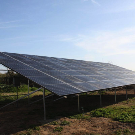
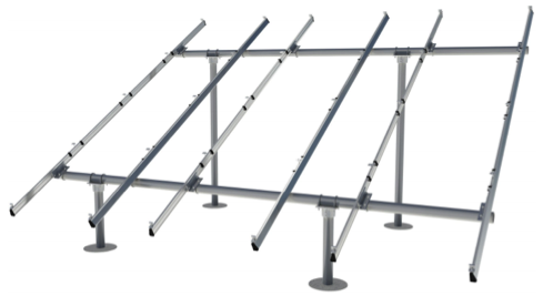
Figure 2. Unirac ULA Double Post (top) and IronRidge GM (bottom)
As mentioned earlier, common foundations consist of driven piles, helical piles, ground screws, concrete footings, concrete ballast or a mixture of these components. The following briefly describes each.
Driven piles are commonly found in larger projects. The piles are constructed of galvanized steel I beams, channel-shaped steel or posts. The piles are driven into the ground using special heavy machinery. Proper soil conditions must be present for driving piles. These conditions include good soil cohesion resulting in high pullout strength as well as limited refusal.
A helical pile is a galvanized steel post with a split disc welded to the bottom at an angle to allow the foundation to move deeper as the post is rotated and driven down. Bobcats or other similar machinery with auger drive units are used to install these foundations. Sandy soils with low cohesion and high water tables are good fits for helical piles.
Ground screws, as the name implies, are large galvanized steel posts with welded or machined threads. Similar to helical pile installations, ground screw installations utilize auger attachments on Bobcats or other like machinery to drive the ground screw into the ground. However, it is common to pre-drill pilot holes when rock or dense refusal is present. Ground screws are a good fit when soil / ground conditions have high amounts of rock, ledge and / or refusal.
Poured concrete footings are very common especially among small ground mount installations. These foundations consist of a galvanized steel post embedded in a concrete form dug into the earth. These foundations are more common to smaller projects because digging holes, aligning posts and handling concrete usually requires a fair amount of labor.
Ballasted foundations are those where pre-cast or poured-in-place concrete ballasts are utilized to support the racking structure. These foundations are good candidates when high amounts of refusal are present or when soil conditions present poor lateral and vertical strength such as brownfields.
Finally, ground mounts are available as pre-engineered systems or custom-built solutions for those faced with extremely difficult terrain. Pre-engineered solutions offer simpler design processes. Manufacturers have performed extensive testing and certification of their pre-engineered systems to meet certain criteria. Companies such as Applied Energy Technologies (AET), IronRidge, Unirac, Orion, DPW Solar and many others offer these solutions. When the site requires a custom-built solution additional design steps will be required to specify the correct components to make up the racking system. Many manufacturers will offer custom design services alongside their pre-engineered systems.
Ground mounts are available in a variety of designs that work with many different foundation types to meet the requirements of almost any site. After performing a thorough site assessment and geotechnical study you can determine the the best ground mount solution for your project.
