Designing systems so that panels operate as closely as possible to their Maximum Power Point is critical to maximizing the performance of the system. A large central inverter such as the Solectria 500XTM has one power point, which means that all panels in the array will produce the same voltage and amperage. If the array is uniform and free from shading, this is generally not a major issue.
However, if there are multiple subarrays with different tilts and/or azimuths, and/or there are shading issues, a more distributed array with a greater number of power points may be preferable. Using multiple string inverters such as the dual-MPPT Solectria 28TL will greatly increase the number of power points, leading to more wattage produced.
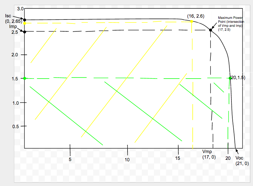
To better understand power points, let’s consider the below diagram (known as the I-V curve) which graphs the amperage and voltage that a sample solar panel will output.

The output of the panel will be anywhere along the curved black line. The left-most point of the graph is the Short Circuit Current (Isc), the point at which amperage is at its maximum and voltage is zero. Below that point on the y-axis is the Imp, which is the ideal operating current of the panel. While technically it is possible for the current to be higher, the lower voltage above the Imp means that the overall wattage produced is less (watts = volts x amps).
Conversely, the right-most point on the graph is the Open Circuit Voltage (Voc), where voltage is at its maximum and amperage is zero. Left of that on the x-axis is the Vmp, which is the ideal operating voltage of the panel. As with the Isc, while it is possible for the voltage to be higher, the lower current past the Vmp produces a lower overall wattage.
The ideal point for the panel to operate at is the Maximum Power Point (MPP, the intersection of the Vmp and Imp). Because the wattage produced is equal to the voltage times the amperage, the point on the graph that allows for the greatest possible area underneath it will produce the most wattage.
For example, the MPP has the coordinates (17, 2.5), meaning that there are 17V and 2.5A produced at that point. 17V x 2.5A = 42.5W.
Other points on the graph will have greater voltages or amperages but less wattage produced. The point in yellow (16, 2.6) produces a wattage of 41.6. The point in green (20, 1.5) produces a wattage of 30. The total area in black under the MPP is greater than the total areas in yellow or green, even though the points in yellow and green have higher amperages and voltages, respectively.
Inverter Photo credit: Power Production Management