With the steep decline of solar module prices, PV system designers are exploring the economic benefits of increasing the array-to-inverter size ratio, or DC load ratio, and leveraging the capability of inverters such as the Advanced Energy® (AE) 3TL product line.
Traditionally, ratios ranging from 1.15 to 1.20 have been used to offset system losses due to temperature, irradiance, soiling, and panel degradation. Optimum ratios were determined by analyzing a system’s annual energy production in terms of kilowatt hours (kWh) per kilowatt peak (kWp DC) of the PV array—a measurement known as specific yield. However, with panels now representing a much smaller percentage of the overall system cost, designers are looking at the smaller incremental cost to increase the array size compared to the gain in kilowatt hours of energy production, and they are identifying opportunities to capitalize on DC load ratios up to and beyond 1.50. This is particularly true for projects where a limit is imposed on the AC output power and the PV plant operator is seeking to maximize energy harvest.
This paper describes some scenarios supporting the trend for higher DC load ratios, and provides example cost modeling to illustrate the potential economic advantages. The paper will also discuss the capability of Advanced Energy’s 3TL inverters to handle higher DC load ratios and some of the key factors that must be taken into account from a system design perspective.
Rationale for High DC Loading
High DC loading is becoming an increasingly common and intentional design decision despite the potential for power clipping. Historically, PV system designers avoided over-sizing the array given the high cost of modules and the desire to optimize string- level output as opposed to system-level output. With the dramatic decline in module prices over the past several years, design philosophies have changed. In many cases today, the lowest project cost per kilowatt hour can be achieved with a high DC load ratio. Figure 1 compares the power output (kW) of a system with high DC loading to that of a system with low DC loading on an Advanced Energy’s 3TL-20 inverter under optimal conditions.

In one system, the array is sized with a low DC load ratio (< 1.20) to avoid power clipping. In the second, additional strings are added for a higher DC load ratio (> 1.20), increasing the overall energy harvest despite the resulting peak power clipping. Figure 1 illustrates that the high DC loading case enables additional energy (kWh) production while not exceeding the maximum power (kWAC) limit. In the high DC loading case, the value of the increased energy production may outweigh the incremental financial investment of adding more modules. Systems with a higher DC-to-AC ratio (DC:AC) have production curves with broader shoulders and the energy production is higher earlier and later in the day.
High DC loading is particularly compelling in cases where there is a limit on AC system size without a corresponding limit on DC system size. AC system size is generally taken as the inverter nameplate power rating. Many utilities will limit the AC rating of a utility interactive photovoltaic (PV) system to the size of the transformer serving the facility. For a 500 kVA service transformer, the AC system size cannot exceed 500 kW. In some cases, no allowance is given for site load, since load dynamics can change over time. The utility perspective is that historical power consumption does not necessarily predict future power consumption. In these cases, the inverter power selection is fixed, based on the interconnection agreement. However, the array size can be increased until all of the physical space available at the site is used or there is no economic payback for installing additional modules.
Other scenarios for high DC loading based on restricted AC system size include special utility requirements, such as redundant relaying or direct transfer trip (DTT) on systems above a certain size. Similarly, there may be physical limitations with the existing electrical infrastructure or building service entrance. Restricting the AC system size may help avoid the high capital costs associated with the addition of specialized equipment or infrastructure upgrades. Furthermore, a feed-in tariff (FIT) with break points based on AC system size may justify keeping the AC system size below a certain threshold and increasing the DC load ratio. Finally, high DC loading can increase output during cloudy weather and maintain higher power outputs as PV modules degrade over time.
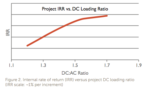
To quantify these ideas, an analysis was done to determine if the value of the increased energy production justifies the additional expense of adding more modules. Projects with DC-to-AC ratios of 1.2, 1.5, and 1.7 were analyzed for initial material and labor costs, and those results were compared to specific yield results from PVSyst for years 1 to 20. In each of these cases, the costs of the inverters, AC switchgear, and permits are essentially constant, and adjustments were made to reflect changes in number of modules and wiring runs. The results of this analysis, shown in Figure 2, support higher DC loading ratios as a way to increase your project’s internal rate of return (IRR). Initial installation costs are greater, as more modules and strings are added to increase the DC-to-AC ratio, but the installed DC cost per Watt decreases. The specific yield increases proportionally with loading ratio, as the addition of strings can offset project efficiency losses over time. In fact, a project with a DC-to-AC ratio of 1.7 will have a higher specific yield in year twenty than a project loaded to 1.2 will have in year one. At DC-to-AC ratios of 1.5 and greater, developers and EPCs reach a point of diminishing economic returns.
Understanding the Different AE 3TL Inverter Models
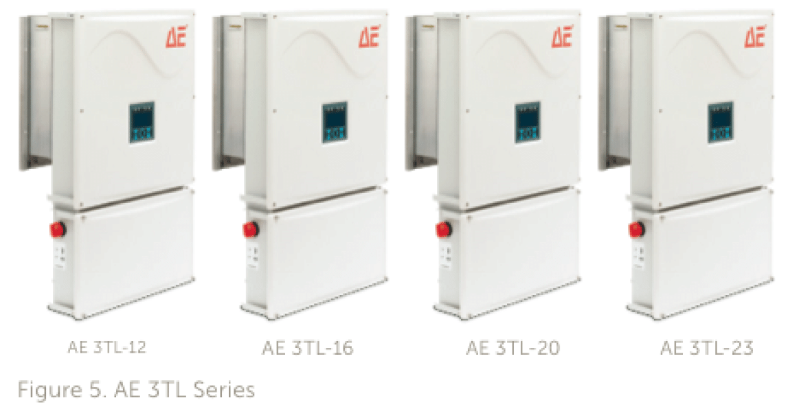
The AE 3TL inverter comes in four different sizes: 12, 16, 20, and 23 kW. Each model is offered with two different DC input configurations (600 Series and 1000 Series), depending on the maximum input voltage limitation of each project:
600 Series
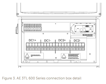
This option is designed for projects utilizing 600 VDC panels and that are therefore limited to 600 Voc. The inverter allows for the connection of a maximum of ten input strings, split evenly between two DC terminal boards, DC1 and DC2 (Figure 3). The max string voltage for each DC terminal board is 500 V open circuit, corrected for temperature. With this topology of dual separable arrays, each of the separate arrays must be run in their own conduit/raceway in order to meet requirements for 600 V systems. Each terminal board is equipped with integrated touch-safe fuse holders for both the positive and negative conductors of every string. The maximum allowable size of the DC fuses is 20 A.
1000 Series
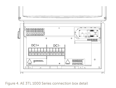
This option is designed for projects limited to 1000 VDC, and utilizes a single-array topology consisting of 1000 Voc strings. The inverter allows for the connection of a maximum of six input strings into a single DC terminal board (Figure 4). There is no requirement for inverter balancing or dual conduit. The terminal board is equipped with integrated touch-safe fuse holders for both the positive and negative conductors of every string. The maximum allowable size of the DC fuses is 20 A.
AE 3TL Inverter Operational Limits
The maximum operating input current is limited by the inverter’s firmware through an input current control loop that limits the DC current to the values listed in Table 1:
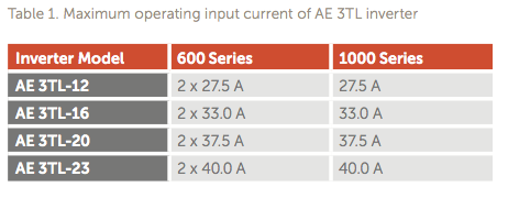
If the input current from the PV array exceeds the inverter’s maximum operating input current, the 3TL will respond by (1) limiting the input current from the PV array to these values, (2) raising the PV array voltage, and (3) finding a new optimal maximum power point (MPP) at which it will operate. This situation is known as clipping and occurs more often when high DC-to-AC ratios are used. In this way maximum output power is maintained, while not exceeding the inverter limits for current.
In the unlikely event that the inverter’s firmware fails to limit the input current from the PV array to the values in Table 1, the inverter components must be able to withstand the over-current without breaking or compromising the safe operation of the device. For this reason, the bus rating of the inverter must be taken into consideration when one is determining the maximum DC loading of the inverters. The bus rating of the AE 3TL 600 Series and 1000 Series is 2 X 76 A and 76 A, respectively. System designers must ensure that the input current from the PV array into the inverter never exceeds these values, after application of the corresponding correction factors.
Inverter Capability to Support DC Loading
The 3TL comes in four different sizes to easily integrate into different applications.

DC loading ratio depends on the inverter selected, the modules used in the system, and the local temperature ranges. This means that a number of factors determine the amount of DC loading that is possible on a project-by-project basis. As a result, the maximum DC loading ratios shown below should be considered a starting point, and specific DC loading calculations should always be performed for each project to determine that the design is within acceptable limits for the four inverter electrical specifications that must be considered when applying Advanced Energy’s 3TL inverters in applications with high DC-to-AC ratios.
- Maximum DC-to-AC load ratio: 1.75:1
- Maximum DC Input Voltage: 500 VDC for the 600 Series and 1000 VDC for the 1000 Series
- Maximum String Fuse Size: 20 A (20 A is optional; 15 A is standard.)
- Maximum Short-Circuit DC Input Current: Do not exceed bus rating of 2 X 76 A for the 600 Series, and 76 A for the 1000 Series.
Conclusion
When considering DC-to-AC loading ratios on 3TL string inverters, it is important to understand that DC losses are lower than what can be expected with central inverters. A distributed approach to inverters provides more autonomy among the array, which maximizes each inverter’s energy harvest. String-level inverters are less susceptible to widespread shading, soiling, and voltage drop. Therefore, the sweet spot for DC-to-AC loading on string inverters will be lower than on centralized systems. By comparing installation costs vs. specific yield, Figure 2 illustrates that IRR can be significantly improved by increasing DC load ratio. The increase is most significant between 1.2 and 1.5, and less significant between 1.5 and 1.75
The AE 3TL inverter’s rugged design allows for more loading than any other string inverter and most central inverters. The excess capacity has been engineered to provide the capability of meeting the robust DC-to-AC loading ratios of today’s market. With the capability to load up to a 1.75 DC-to-AC ratio, the 3TL can meet the requirements for any project and maximize project return.
Please visit contact your Greentech Renewables sales representative at 800-409-2257 or apply for dealer pricing online.
