
Evaluating the ability of a roof to support solar modules requires assessing the condition and construction of the roof, calculating the weight impact of the solar modules and support structures, and taking into account the potential impact of snow and wind. Typical solar modules weigh 20 to 50 pounds each and are distributed evenly across a roof along with the racking systems that support them. By dividing the weight of the modules and underlying racking by the area of the modules, we generally find that the combined weight of solar modules and the racking that supports them puts about 3-4 pounds of weight per square foot on a roof. Most structures built after 1970 are designed to support loads far greater than this. Local permitting rules must be consulted, but generally such loads are acceptable.
However, this assumption of a distributed load is generally not valid. The weight of the modules is actually distributed to a limited number of mounting points and installers generally try to minimize this number and as a result the number of roof penetrations, thus reducing the potential for roof leaks. This strategy has a downside that it can create large point loads on the trusses that support the racking.
Assessing the extent of these point loads involves adding up the contributions of the roofing materials themselves as well as the solar equipment. The uniform dead load on a rafter (expressed in pounds per linear foot or PLF) is calculated by multiplying the uniform dead load pressure (in pounds per square foot or PSF) by the rafter spacing and adding the weight of the rafter. A typical value for the roofing material itself is 10 PSF. Therefore, a typical roof with 24-inch rafter spacing and rafters that weight 2 PLF would have a dead load of 10 x (24/12) + 2 = 22 PLF before the solar equipment was added. For a 16-foot rafter, this then results in a 352 lbs. dead load. Adding the modules would increase the dead load according to the same sort of calculation. The PSF of the modules (typically 3) is multiplied by expanse of modules supported by each rail times the rail spacing. As an example, if 5 feet of modules sit on two rails spaced 4 feet apart, the resultant point load would be 3 x (20/2) x 4 = 30 lbs. Thus, in this example, the dead load is increased by 12.5%.
Residential applications typically involve a pitched roof on which solar modules are mounted parallel to the pitch. If the slope of the roof is not too high, the modules can hold snow and the weight loads can increase dramatically. Such a live load can be much greater than the previously calculated dead load because snow can weigh much more than the modules. In addition, there are circumstances under which snow loads will be greater than what would be calculated from the amount of snow on the ground including the effects of drift or sliding snow. The actual calculation is the same as above but estimating potential snow loads requires analysis of the roof structure and detailed local climate information.
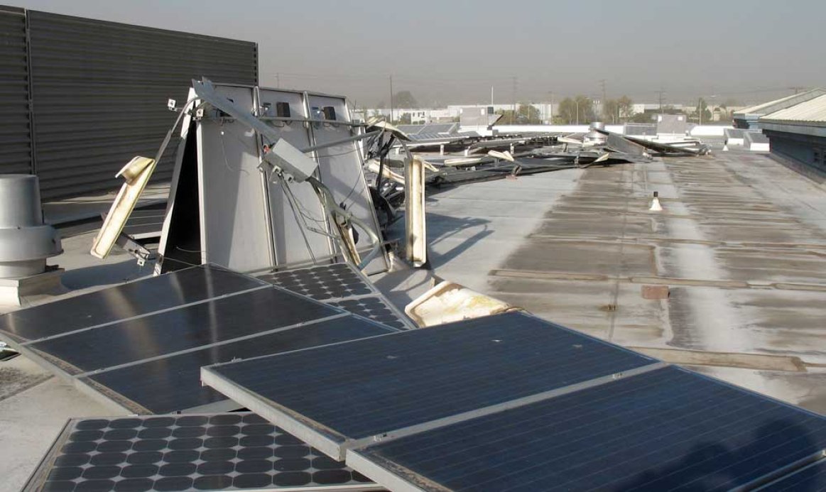
An even greater concern is wind loading caused by uplift accumulated through the solar array and acting on the attachment points that support the solar modules. In some cases, solar modules can act as a sail and the wind from under the modules can create very high uplift loads. With enough upward force, solar modules can come loose from the roof and it is even possible that the roof itself can be pulled off along with the solar modules. Calculating wind uplift forces (Fw) is similar to other load calculations (it is a product of the local wind force multiplied by the module length multiplied by the rail spacing) but is complicated by the fact that these forces vary significantly depending upon where the modules and rails are located on the roof.
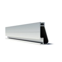
IronRidge, and other solar racking companies, provides a number of tools for calculating such parameters as the total uplift from wind and down force from snow. These values vary tremendously from location to location and must be considered carefully for the specific site of the system. In places where there may be extreme winds (such as in Florida) or where there can be heavy snow (such Michigan), the solar contractor, architect or engineer may need to design with additional and specialized support for solar modules. Solar modules are intended to stay in place for decades; properly attaching them to the roof is essential for this long operating life.
