Battery storage systems are becoming increasingly prevalent in commercial applications, providing a reliable backup power source and enabling more effective use of renewable energy. A critical aspect of these systems is the management of fault current on the DC side, particularly in configurations with multiple battery packs paralleled into a DC battery combiner. This article provides an overview of the fault current design considerations for such systems.
Understanding Fault Current in DC Systems
Fault current is the unintended current that flows through a system due to a fault, such as a short circuit or equipment failure. In battery storage systems, unmanaged fault currents can lead to severe damage, safety hazards, and operational downtime. It is essential to design the system to handle potential fault currents effectively to ensure safety and reliability.
Typical Components in Fault Current Design
Multiple batteries in parallel
Commercial battery storage systems often use multiple battery packs connected in parallel to increase capacity and ensure redundancy. This configuration impacts fault current levels, as each battery pack can contribute to the total fault current. Properly managing the fault current involves careful consideration of the battery pack specifications, connections, and protection devices.
Battery Combiner
A battery combiner is used to aggregate the outputs of multiple battery packs into a single DC bus. It plays a crucial role in fault current management by providing a centralized point for monitoring and protection. The design of the battery combiner must account for the maximum potential fault current from all connected battery packs. This is harder than it sounds because there aren’t many available options above 1000A at 48V.
Fusing
Fuses are essential protection devices in DC systems. They are designed to interrupt excessive current flow, protecting the system from damage. Selecting the appropriate type and size of fuses is critical to ensure they respond correctly to fault conditions. In commercial systems, high-current fuses that can handle the combined output of multiple battery packs are often required. It is important to know the kAIC rating of the fuses - standard fuses may not be suitable.
Wiring
The wiring in a battery storage system must be capable of carrying the normal operating current and any potential fault current. Proper wire sizing and material selection are essential to minimize resistance and heat generation. Additionally, routing and securing the wiring to prevent mechanical damage and reduce fault risks is important. Typically, the wiring itself is not an issue since it will be protected by a suitable kAIC OCPD device, but mechanical protection and torque values at terminals can be very important to avoid fault currents in the first place.
Designing for Fault Current
System Analysis
The first step in fault current design is to analyze the system to determine the potential fault current levels. This involves calculating the worst-case scenario where all battery packs contribute to the fault simultaneously. Tools like circuit simulation software can aid in performing these calculations accurately.
Calculating fault current is fairly straightforward; we need to know the internal resistance of the battery and the nominal voltage. With those two values, we can apply Ohm’s Law: Current (I) is equal to the voltage (V) divided by the resistance, R.
The problem is that we can’t know the resistance of the battery without testing an actual battery unit or getting the information directly from the manufacturer. Since this is a practical guide for designing with commercially available products before we have possession of them, there are only two actual methods of determining battery fault current:
- Read the manual
- Ask the manufacturer
Protection Strategies
Once the potential fault current is determined, the next step is to implement protection strategies. Overcurrent protection devices (OCPDs) such as fuses and circuit breakers must be appropriately sized and coordinated with other system components to ensure they interrupt the fault current before any damage occurs. Design for usability: If the battery enclosure is ever to be opened, it should have a plexiglass dead front.
Best Practices
Implementing best practices in design and maintenance can significantly enhance fault current management. Regular inspection and testing of protection devices, ensuring proper connections and secure mounting of components, and using high-quality materials can all contribute to a safer and more reliable system. For example, if the battery has a plexiglass dead front, it should always be in place.
Case Study: Commercial Battery Storage System
Consider a commercial battery storage system with six 5 kWh battery modules connected in parallel. The battery combiner aggregates these packs into a single DC bus for connection to an inverter. The system design process involves the following steps:
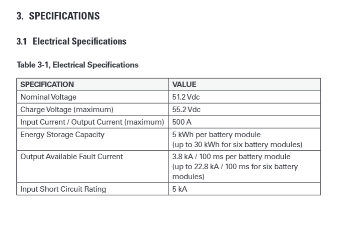
1. System Specifications:
- Nominal Voltage: 51.2 Vdc
- Charge Voltage (maximum): 55.2 Vdc
- Input Current / Output Current (maximum): 500 A per module
- Energy Storage Capacity: 5 kWh per module (up to 30 kWh for six modules)
- Output Available Fault Current: 3.8 kA / 100 ms per module (up to 22.8 kA / 100 ms for six modules)
- Input Short Circuit Rating: 5 kA
2. Calculating Potential Fault Current:
- Each battery module can deliver up to 3.8 kA in a fault condition.
- With six modules, the total potential fault current could reach 22.8 kA (3.8 kA x 6).
3. Selecting Fuses:
- To protect each battery module, Littelfuse’s KCC series high-speed fuses can be used.
- For this example, the KCC-500 fuse is chosen, which is rated at 500A with a breaking capacity (kAIC rating) of 20 kA.
- This means it can safely interrupt up to 20,000A of fault current, providing adequate protection for each battery module.
4. Designing the Battery Combiner:
- The combiner is equipped with busbars and connectors rated to handle the maximum fault current.
- Additionally, it includes monitoring equipment to detect and respond to fault conditions.
- It needs to be a listed device or it needs to be designed and built in a listed panel shop.
5. Sizing the Wiring:
- Wires are selected based on their current-carrying capacity and ability to withstand the fault current without excessive heating or damage - as usual in any wire design.
- Proper insulation and protective conduit are used to enhance safety.
6. Implementing Redundancy:
- To ensure reliability, the system includes redundant fuses and monitoring circuits, providing backup protection in case of a primary device failure.
Common Challenges and Solutions
High Fault Current Scenarios
In commercial systems, managing high-fault currents can be challenging. One solution is to use modular battery packs with integrated protection devices, which can limit the fault current at the source. Additionally, designing the system with sufficient clearances and robust components can help handle higher fault currents safely.
Takeaway: You may need a custom-designed battery combiner
Managing System Complexity
Complex systems with multiple battery packs require careful coordination of protection devices and monitoring equipment. Implementing centralized monitoring and control systems can simplify management and improve fault response times.
Future Trends and Developments
As with most new renewables products, technological advances are continually improving available solutions to fault current management in DC systems. Innovations in materials, such as advanced fuses and circuit breakers, offer better performance and reliability. Emerging standards and regulations are also shaping the design and implementation of fault current protection in battery storage systems, ensuring higher safety and efficiency levels. In summary, as more custom DC combiners or battery module OCPD solutions are developed, we are more likely to see the standard, listed products to purchase ‘off the shelf’.
Conclusion
Effective fault current design is crucial for the safety and reliability of commercial battery storage systems.
- Is my DC equipment protected from accidental or mechanical faults?
- Is my DC equipment protected from fault current in the case of a fault?
- Is my DC combiner a Listed Device ?
For follow-up questions or further design or logistical support, contact our Design Services team.